
- Products
- Thruster Brake
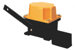
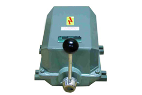
Thruster Brake
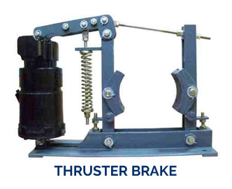
While this is going on, the brake lever on the other side of the wheel (Brake Drum) is retracted. The brake lever at the thruster begins to move when the first lever reaches the stop on the brake base member. The Thruster and the brake are adjusted in such a manner that they reserve about 1/3 of the stroke for compensation of the wear of the brake linings.
The thruster cylinder accommodates a centrifugal pump and a piston with two push-rods extending outside through thruster cover and transmitting effort to the brake. The design is compact and has a long life. It is very easy to maintain. Main components used are of high quality cast iron and steel. The Thruster is operated by an integral three phase squirrel cage motor. These thruster brakes are suitable for 400/440 Volts, 3 Phase A.C. supply for a wide range of drum sizes, from 100mm to 600 mm in diameter.
The Related Motor Torque is given by :
T= 716.2 X HP % RPM OR 9.25 X KW % RPM
 022 28502162


